A Homemade Slicer for 3D Printing
- Joelle McDonald

- Mar 13, 2025
- 10 min read
Updated: Mar 19
In this blog post I will be using Grasshopper and Rhino to create a 3D slicer that communicates with a Prusa MK3 Printer. A 3D slicer takes a 3D object as input, then turns it into instructions that a 3D printer knows how to follow. These instructions are called G-code. In this project, I use Grasshopper to create an algorithm for slicing a 3D object, in this case a cylinder, then use Python code to turn those slices into G-code for printing.
Tool and Materials Used: Grasshopper, Rhino, Python, Pruka MK3 3D Printer, PLA
Resources Referenced: Advanced 3D Printing with Grasshopper, Clay and FDM, by Diego García Cuevas and Gianluca Pugliese
GitHub Links: Grasshopper Script, Python Algorithm, G-code with 100% infill, G-code with 50% infill
Task 1: Creating a Slicing Algorithm
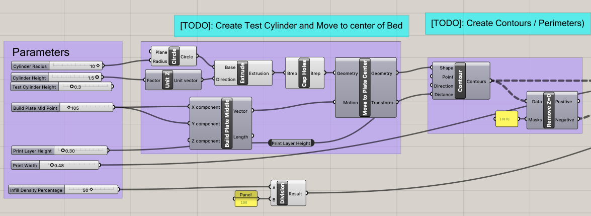
To create my slicer, I began by using the 3D printing parameters I was given and created a cylinder as the object I would be slicing. Some of these parameters were included in the beginning of my Grasshopper script because they were involved in creating the slices and contours my slicer generates, namely layer height and the extrusion width. Other parameters were related to the G-code itself, so were inputed into the Python code block. .

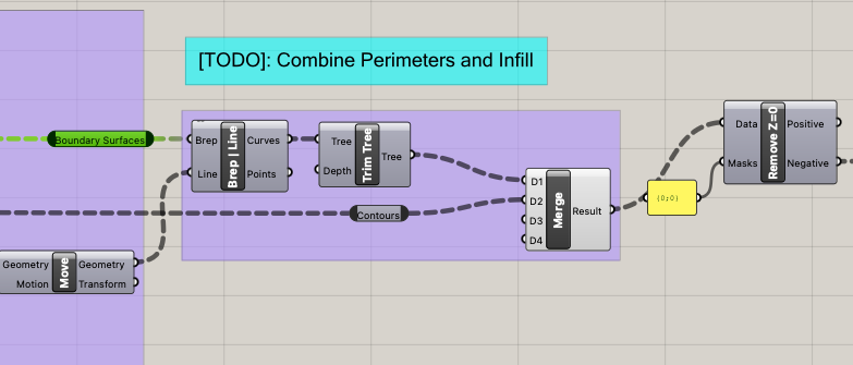
By applying the correct parameters, I created the resulting Grasshopper Script. To view the full Grasshopper script, visit it's GitHub page here.
Screenshots of Grasshopper Script (click to view full images)


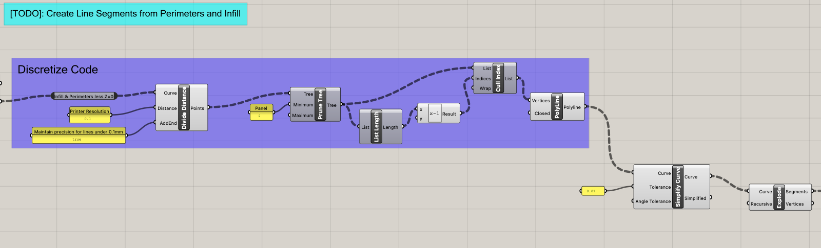


Once I had created my slicer with Grasshopper code, I needed to confirm it was working correctly using the Rhinoceros generation it created. Each generation should have a circular perimeter and a series of evenly spaced infill lines per layer. The circular perimeter should present with many points along it, as it is a polyline and not a smooth curve. My slicer was working correctly when I tested it with 1 and 5 layer cylinders, so I was prepared to move on to creating my algorithm for generating G-code.

Task 2: Create an Algorithm for G-code Generation
After using Grasshopper to create the line segments my 3D printer would follow, I needed to turn those line segments into G-code the 3D printer can understand and implement. To do this I used a Python script block in my Grasshopper document.
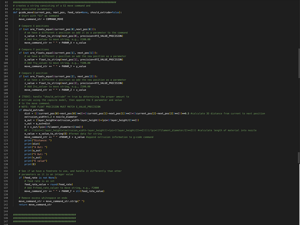
I began by creating the function that would determine if the printer nozzle is in the correct location and how much material to extrude as it moved. The most complicated component to code was information to help the nozzle understand how much material to extrude at a given time. To achieve that, I first determined the formula for Le, the length of material that should enter the nozzle for extrusion.

The move function serves as a set up function for generating G-code in the following function. It helps to compare XYZ positions, set up feed rate infrastructure, and create strings.
Next, I created the generate_gcode function. This function identifies the nozzles existing location, compares it to the next location the nozzle should be, and orchestrates the correct movement between the two. It than appends that movement to the G-code so that each time the loop runs on a new segment, the instructions for the next line are being added to the G-code. It also combines the start and end G-code lines, which are input in a panel and conduct operations like heating the bed before printing and turning off the bed heat after.

The G-code generated by the Python block is printed to a panel in Grasshopper, as pictured below.

Here, I have the full Python code both printed here in the expandable list and linked on GitHub:
Full Python Code for G-code Generation (also linked on GitHub here)
"""
This file contains parameters, helpers, and setup to
create a basic gcode generation algorithm from line segments.
The main
Inputs:
lines: the line segments to be converted into gcode commands for extrusion
nozzle_diameter: the diameter of the 3D printer's nozzle
filament_diameter: the diameter of the 3d printing filament
layer_height: the height of each layer in the print
extrusion_width: the width of the extruded line from the printer
travel_feed_rate: the speed at which the extruder moves in X and Y
layer_change_feed_rate: the speed at which the extruder moves when
changing layers in the Z direction
extrusion_feed_rate: the speed at which the extruder move when extruding
Output:
gcode_output: a string with gcode commands separate by new-lines"""
__author__ = "mrivera-cu"
import rhinoscriptsyntax as rs
import math
pi=math.pi
########## CONSTANTS BELOW ###############
# GCODE COMMANDS
COMMAND_MOVE = "G1"
# GCODE PARAM NAMES
PARAM_X = "X"
PARAM_Y = "Y"
PARAM_Z = "Z"
PARAM_E = "E"
PARAM_F = "F"
# Separates commands
COMMAND_DELIMITER = "\n"
# Precision for converting floats to strings
E_VALUE_PRECISION = 5
XYZ_VALUE_PRECISION = 3
# Float equality precision
FLOAT_EQUALITY_PRECISION = 5
# Converts a float (f) to a string with some precision of decimal places
# For example:
# Input: f=0.1234, precision=3
# Output: "0.123"
def float_to_string(f, precision=XYZ_VALUE_PRECISION):
f = float(f)
str_format = "{value:." + str(precision) +"f}"
return str_format.format(value=f)
# Helper to convert the E value to the proper precision
def e_value_to_string(e):
return float_to_string(e, E_VALUE_PRECISION)
# Helper to convert the XYZ value to the proper precision
def xyz_value_to_string(e):
return float_to_string(e, XYZ_VALUE_PRECISION)
#########################################################################
# Helper function to compare floats in grasshopper/python due to float precision errors
def are_floats_equal(f1, f2, epsilon=10**(-FLOAT_EQUALITY_PRECISION)):
f1 *= 10**FLOAT_EQUALITY_PRECISION
f2 *= 10**FLOAT_EQUALITY_PRECISION
return math.fabs(f2 - f1) <= epsilon
# Helper function to compare if two points are equal (have the same coordinates)
# by handling float precision comparisons
def is_same_pt(ptA, ptB):
return are_floats_equal(ptA[0], ptB[0]) and are_floats_equal(ptA[1], ptB[1]) and are_floats_equal(ptA[2], ptB[2])
########################################################################
# creates a string consisting of a G1 move command and
# any associated parameters
def gcode_move(current_pos, next_pos, feed_rate=None, should_extrude=False):
# Start with "G1" as command
move_command_str = COMMAND_MOVE
# Compare X positions
if (not are_floats_equal(current_pos[0],next_pos[0])):
# we have a different x position so add it as a parameter to the command
x_value = float_to_string(next_pos[0], precision=XYZ_VALUE_PRECISION)
# Add X<x_value> to move string, e.g., X100.00
move_command_str += " " + PARAM_X + x_value
# Compare Y positions
if (not are_floats_equal(current_pos[1], next_pos[1])):
# we have a different y position so add the new position as a parameter
y_value = float_to_string(next_pos[1], precision=XYZ_VALUE_PRECISION)
# Add Y<y_value> to move string, e.g., Y100.00
move_command_str += " " + PARAM_Y + y_value
# Compare Z position
if (not are_floats_equal(current_pos[2], next_pos[2])):
# we have a different z position so add the new position as a parameter
z_value = float_to_string(next_pos[2], precision=XYZ_VALUE_PRECISION)
# Add Z<z_value> to move string, e.g., Z100.00
move_command_str += " " + PARAM_Z + z_value
# [TODO]: handle "should_extrude" == true by determining the proper amount to
# extrude using the capsule model, then append the E parameter and value
# to the move command.
# NOTE: YOUR FLOAT PRECISION MUST MATCH E_VALUE_PRECISION
if should_extrude:
dist = (((current_pos[0]-next_pos[0])**2)+((current_pos[1]-next_pos[1])**2)+((current_pos[2]-next_pos[2])**2))**0.5 #calculate 3D distance from current to next position
extrusion_width=1.2 * nozzle_diameter
a_out = (layer_height*(extrusion_width-layer_height))+(pi*((layer_height/2)**2))
v_out = a_out*dist
E = v_out/(pi*((filament_diameter/2)**2))
#E = ((dist*((layer_height*(extrusion_width-layer_height))+(pi+((layer_height/2)**2))))/(pi*((filament_diameter/2)**2))) #calculate length of material into nozzle
e_value = e_value_to_string(E) #format data for string
move_command_str += " " +PARAM_E + e_value #append extrusion information to g-code command
print("Distance: ")
print(dist)
print("A Out: ")
print(a_out)
print("V Out: ")
print(v_out)
print("E value")
print(E)
# See if we have a feedrate to use, and handle it differently than other
# parameters as it is an integer value
if (feed_rate is not None):
# feed rate is an int
feed_rate_value = round(feed_rate)
# Add F<feed_rate_value> to move string, e.g., F2000
move_command_str += " " + PARAM_F + str(feed_rate_value)
# Remove excess whitespace on ends
move_command_str = move_command_str.strip(" ")
return move_command_str
############################################
############################################
############################################
''' Here's the main method of the script that uses the helper methods above '''
def generate_gcode():
# [TODO]: Implement the algorithm to generate gcode for each layer by
# first to moveing to the layer height, then moving to each line segment.
# Once at a line segment, you should move and extrude along it,
# then move (travel) to the next line until there are no lines left
# For each of these movements, you should append the command to
# the list: `all_move_commands`
current_position = [0, 0, 0] # start extruder at the origin
all_move_commands = [] # list to hold for all the move commands
for i in range(0, len(lines)):
# Get pts of the line segment
line = lines[i]
line_start_position = line.From
line_end_position = line.To
# [TODO]: Handle moving to the next layer (Z Position)
# NOTE- ALL Z MOVEMENTS SHOULD:
# 1) BE INDEPENDENT MOVES(e.g., G1 Z# and not move with other positions like XYE)
# 2) USE THE `layer_change_feedrate`
# 3) BE IN INCREASING ORDER
if (not are_floats_equal(current_position[2], line_start_position[2])):
if line_start_position[2] > current_position[2]:
move_to_z_start_command = gcode_move(current_position, (current_position[0], current_position[1], line_start_position[2]), feed_rate = layer_change_feed_rate) #Move to the the line_start_position[2] (z-value)
print("Z-Move Command:", move_to_z_start_command)
all_move_commands.append(move_to_z_start_command) # Append command
else:
print("Error in Z-position ordering")
current_position = (current_position[0], current_position[1], line_start_position[2])
# Now if our current_position is not the start of our line segment
# we need to move (travel) to the line segment's starting point
if not is_same_pt(current_position, line_start_position):
# [Move to the the line_start_position
move_to_line_start_command = gcode_move(current_position, (line_start_position[0], line_start_position[1], current_position[2]), feed_rate = travel_feed_rate)
# Append command
all_move_commands.append(move_to_line_start_command)
current_position = line_start_position
# [TODO]: Once our extruder is at the start of the line, create a
# command to move AND extrude along
# the line segment using `extrusion_feed_rate`
if is_same_pt(current_position, line_start_position):
move_and_extrude_line_segment = gcode_move(current_position, line_end_position, feed_rate = extrusion_feed_rate, should_extrude=True)
# [TODO]: Append the move command across the line segment
all_move_commands.append(move_and_extrude_line_segment)
# [TODO]: Update the current position of our extruder to be at the end of the line
current_position = line_end_position
# End of for-loop above -- now create the full set of commands
# [TODO]: Once you have all of the move commands stored as a list in
# `all_move_commands`, combine the `start_gcode_lines`, `all_move_commands`, and `end_gcode_lines`
# into one list called `gcode_lines`
gcode_lines = []
gcode_lines = start_gcode_lines + all_move_commands + end_gcode_lines
# --- DO NOT EDIT BELOW ----
# The takes the combined gcode_lines list and creates a string containing each line
# separated by a COMMAND_DELIMITER (the new-line character), and sets it
# to the `gcode_output`variable of this component
output = COMMAND_DELIMITER.join(gcode_lines)
return output
''' RUN THE MAIN FUNCITON ABOVE - DO NOT EDIT '''
# this sets the gcode commands to be the the `gcode_output` variable of this grasshopper component
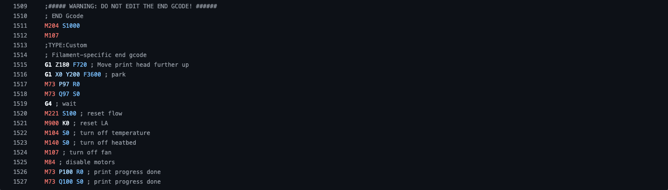
gcode_output = generate_gcode()The G-code generated for the primary cylinder (5 layers, height 1.5mm, infill 100%) is 1527 lines, so in lieu of including all of the code directly in this post, I have linked the full G-code file here for viewing and included a gallery images of the start code, a sample of the move instructions, and the end code. Click the image below to expand it and use the arrows to navigate the photos.


Task 3: Export and Test G-code
In order to export the G-code my python code now generates, I used the Pancake plug-in from Food4Rhino. This allows for outputs generated in the Grasshopper workspace to be easily saved with specific file types. Below you can find the Pancake code I used for export. Each time I pressed the "True Only Button," a new export would be created, overwriting any previous exports.

To view the G-code exported by my Pancake code, please visit this GitHub link. The G-Code at that link uses a 100% infill setting.
Once I had my G-code exported, I needed to verify the tool path was accurate and that it would not damage the 3D printed I was planning to use.
First, to verify the tool path and extrusion, I used ZupFe, an online 3D print simulator that allows layer-by-layer tool path analysis. I have included screenshots of the simulted layer-by-layer extrusions below, which I used to verify my algorithm and G-code were behaving as expected.

Once I was satisfied that the tool path and extrusions matched my intent, I moved on to verifying my G-code would not damage a Prusa MK3 printer. To do this I used a G-code validation created by CU's Utility Research Lab to run tests on our G-code like setting the minimum bed temperature and ensuring all layers print in increasing Z-order. The tool can be found here. Once my code passes all 25 tests, I was prepared to test my G-code on a printer.

Task 4: Fabricate a Test Cylinder
Finally, to put my G-code to the real test it was time to print it on a Prusa MK3 printer. In order to compare my slicer to a standard market slicer, I first printed a cylinder with the same parameters (1.5mm tall, 10mm radius) sliced by Prusa Slicer. I used 15% infill, no brim or supports, and the 0.3mm draft setting.

Comparison between Prusa Slicer and my Own
The cylinder sliced by Prusa printed in about 5 minutes. My G-code with 100% infill took significantly longer due to the infill lines lacking a serpentine structure. The final outputs were, however quite similar. Both were the same size and shape with similar edge appearances. The primary different other than print speed is that the Prusa-sliced cylinder printed with smoother surfaces than my sliced cylinder. I suspect that is because the serpentine line structure used by Prusa allows for more continuity of material flow. Each interruption in extrusion creates an opportunity for stringing, globing, or other sources of unevenness. Prusa's slicer had fewer extrusion interruptions and therefore printed a smoother end piece.
Extra Credit: Adding an Infill Density Percentage Parameter
One flaw in a slicer generated without infill density parameters is that they can only print solid objects, resulting in material waste and longer print times. It is easy to add a print infill parameter. To do this I simply multiplied the decimal form of the print percentage by the print width and used the result the same way a 100% infill-only algorithm would use print width to space its infill lines.


The code then allows for the manipulation of the infill density. I set the infill density at 10%, 20%, 50%, and 100% and got the following results:

Making adjustable infill density allows for improved flexibility of the slicer to accommodate a wider variety of print resolution goals while saving print material and time.
Conclusions
While a good exercise in understanding 3D printing and G-code file structures, the results achieved by my own slicer as it stands are not as good as those achieved by commercially available slicers today. With additional time investment I could close that gap by adding more options and functionality to my own slicer with tools like serpentine infill printing, other infill pattern options, support tools, and more. The flexibility and reliability make existing mass market slicers very appealing for standard use of 3D printers. However, for more experimental prints or for functions not currently supported by widely available slicers, being able to create your own slicer is a valuable skill.


Comments